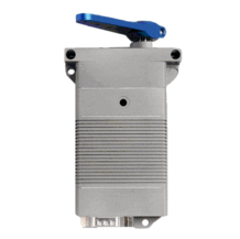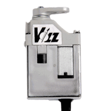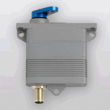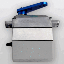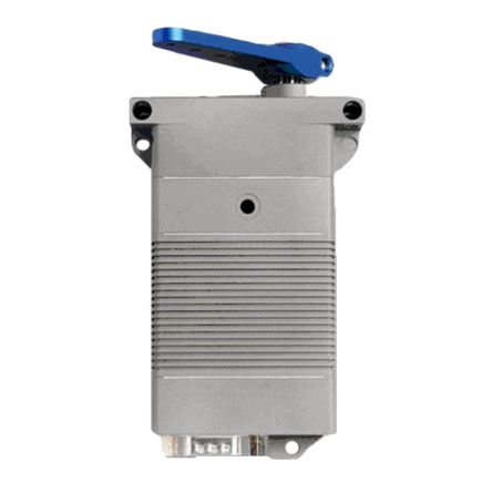
DA 30-30-5224 Volz Servo
DA 30-30-5224 Volz Servo guarantees maximum safety and reliability; features a brush less motor and a contactless wear free position sensor.
View cart
- Description
- Specifications
Description
DA 30-30-5224 Volz Servo guarantees maximum safety and reliability. The DA 30 features a brushless motor and a contactless wear free position sensor. This means maximum service life with the greatest‐possible power delivery and its design prevents electromagnetic emissions (EMI) caused by brush sparking. The housing made of saltwater‐resistant aluminum is HART‐coat treated, meets the IP‐67 standard for water and dust sealing and provides an integrated Sub‐D connector (MIL spec. circular connector or cable gland on request). Brackets integrated in the housing for horizontal and vertical assembly. 8‐fold, ball‐bearing supported, steel gear train, drive shaft with ANSI multi‐tooth. To guarantee maximum safety and reliability, our
DA 30-30-5224 Volz Servo features a brushless motor and a contactless wear free position sensor. This means maximum service life with the greatest‐possible power delivery and its design prevents electromagnetic emissions (EMI) caused by brush sparking. The housing made of saltwater‐resistant aluminum is HART‐coat treated, meets the IP‐67 standard for water and dust sealing and provides an integrated Sub‐D connector (MIL spec. circular connector or cable gland on request). Brackets integrated in the housing for horizontal and vertical assembly. 8‐fold, ball‐bearing supported, steel gear train, drive shaft with ANSI multi‐tooth.
The DA 30 series can be equipped with a standard PWM input (Pulse Width Modulation) that has two different interfaces: a differential, galvanic isolated interface (Opto‐Coupler) and a single‐ended interface with CMOS levels that is also used to program the servo parameters. It includes analog position feedback to detect the drive shaft position. A differential RS‐422 PWM interface can be chosen instead of the opto‐coupled interface.
DA 30 with digital serial command interface (RS‐485) receives its commands via a CRC secured protocol. It can return not only the shaft position in digital format, but also several diagnostic data such as the level of the supply voltage, current consumption and the temperature of the motor and electronics in digital form (optionally also the humidity within the actuator case). These kind of diagnostic capabilities help to determine the health state of the actuators before, during and after deployment.
About Volz Servos
A servo from Volz excels due to the simplicity of its design while simultaneously maximizing positioning force, reliability and durability. Moreover, a variety of electric interfaces makes it possible, for instance, to monitor the operating condition of the servos by reading out the current consumption, the internal temperature and humidity, etc.
Every actuator compromises a DC motor, a gear train and control electronics governed by microprocessors with integrated position feedback. These are electromechanical servo units that precisely position a radial output drive.
Depending on the type of actuator, the maximum travel in the standard configuration varies between 90° and 170°. Versions with larger travel of up to 330° or “Multiturn” versions can be provided on request.
About Volz
Founded in 1983, Volz Servo began designing, manufacturing and marketing exclusively electro mechanical actuators/servos worldwide. Volz has developed a product range that meets most customer requirements concerning maximized torque, speed, efficiency, reliability, and durability at minimized volume/weight, component and development costs. Volz has a reputation for being experts in the market of compact, highly efficient actuators/servos.
Operating Data
| Supply Voltage (rated) | 28 V DC |
| Supply Voltage Range | 24…32 V DC |
| Standby Current at rated voltage | Rated Current at rated voltage 1.3 A |
| Peak Current at rated voltage | 2.6 A |
| Rated Torque at rated speed | 80Nm (70.8 lbf-in) |
| Peak Torque at rated voltage | 16.0 Nm (141.6 lbf-in) |
| No Load Speed at rated voltage | 230°/s |
| Rated Speed at rated torque | 150°/s |
| Default Travel Angle | ±45° = 90° total travel |
| Max. Standard Travel Angle | ±50° = 100° total travel |
| Extended Travel Angle (optional) | ±85°=170° total travel |
| Backlash (mechanical) | 0.5° |
| Position Error under Temperature | ≤±1.0° |
| Operating Temperature Range | -30°C … +70°C (-22°F…+158°F) |
| Storage Temperature | -55°C…+85°C (-67°F…+185°F) |
Command Signal
| Signal Voltage | TTL-Level HIGH: min. 3.5V; max 5.5V |
| TTL-Level LOW: min 0.0V; max 1.5V | |
| Frame Rate | 2.6…2000 ms |
| Valid Pulse Lengths | 0.9…2.1 ms |
| Pulse Length for Position Left/Center/Right | 1.0/1.5/2.0 ms |
| Resolution | ≤1.0us |
| RS 485 COMMAND SIGNAL | Valid for all versions with RS 485 Command Signal |
| RS 485 | RS 485 Redundant |
| Baud-Rate | 115200±1.5% bits/s |
| Protocol (documentation available) | 6 Byte (incl. 2 byte CRC) |
RS 485 Protocol Specifications
| RS 485 | RS 485 Redundant |
| Number of Data Bits | 8 |
| Number of Stop Bits | 1 or 2 |
| Parity | None |
Command / Response Frame
| Byte # | Description |
| 1 | Command / Response-Code |
| 2 | Actuator ID |
| 3 | Argument 1 |
| 4 | Argument 2 |
| 5 | CRC High Byte |
| 6 | CRC Low Byte |
Material & Protective Features
| Case Material | Saltwater resistant Aluminum Alloy |
| Splash Water Resistance | IP 67 waterproof to 1m depth |
| Case Surface Treatment | HART-Coat |
| Salt Water Resistance | >100hr. Salt Water Spray |
| Standard – Case Material | |
| EMI / RFI Shielding | Case Shielding |
| Motor Type | Brushed DC Motor |
| Gear Set Material | Hardened Steel |
| Position Sensor | Contactless |
| Position Feedback | Standard |
| RS 485 Communication Interface | Optional |
| Humidity Sensor | Optional |
| Temperature Sensor | Standard – Motor and PCB |
Dimensions
| Case Dimensions | 114.6 mm x 67.5 mm x 30.0 mm ±0.2 mm (4.512 in x 2.658 in x 1.181 in ±0.008in) |
| Weight | 640g (22.6 oz) ±10% |
| ELECTRICAL CONNECTION OPTIONS | DA 30.30.5224.1_ |
| Standard Connector | |
| Manufacturer | ITT Cannon |
| Type | DEMM-9PE |
| Mating | D-SUB DE-9f |
PWM-OPTO Pin Assignment
| 1 | PWM (AO) | Command Signal – Anode Optocoupler |
| 2 | PWM (CO) | Command Signal – Cathode Optocoupler |
| 3 | Diff FB A | Differential Position Feedback Signal – Output A |
| 4 | to Pin 7 | Connect to pin 7 (Supply Ground) |
| 5 | Case GND | Case Ground |
| 6 | +V DC | Supply Voltage |
| 7 | GND | Supply Ground – Signal Ground |
| 8 | Pos FB | Single Ended Position Feedback Signal |
| 9 | Diff FB B | Differential Position Feedback – Output B |
| RS 485 Pin Assignment | ||
| 1 | NC | Do not connect |
| 2 | NC | Do not connect |
| 3 | Diff FB A | Differential Position Feedback Signal – Output A |
| 4 | PWM | Command Signal |
| 5 | Case GND | Case Ground |
| 6 | +V DC | Supply Voltage |
| 7 | GND | Supply Ground – Signal Ground |
| 8 | Pos FB | Signal Ended Position Feedback Signal |
| 9 | Diff FB B | Differential Position Feedback Signal – Output B |
Integrated Connector
| PWM-RS 422/TTL Pin Assignment | ||
| 1 | RS 422/PWM | Non-inverted RS 422-input |
| 2 | RS 422/PWM | Inverted RS 422-Input |
| 3 | Diff FB A | Position Feedback Signal – Output A |
| 4 | TTL/PWM | Command and Parameter Input |
| 5 | Case GND | Case Ground |
| 6 | +V DC | Supply Voltage |
| 7 | GND | Supply Ground – Signal Ground |
| 8 | Pos FB | Single Ended Position Feedback Signal |
| 9 | Diff FB B | Differential Position Feedback Signal – Output B |
Rs 485 Interface (2-Wire) DA 30.30.5224.3…
| RS 485 (2-Wire) Pin Assignment | ||
| 1 | RS 485 A | Non-Inverted Input/Output |
| 2 | RS 485 B | Inverted Input/Output |
| 3 | – | Do not connect |
| 4 | +V DC (2) | Supply Voltage – Secondary |
| 5 | Case GND | Case Ground |
| 6 | +V DC (1) | Supply Voltage – Primary |
| 7 | GND (1) | Supply Ground – Signal Ground – Primary |
| 8 | GND (2) | Supply Ground – Signal Ground – Secondary |
| 9 | – | Do not connect |
RS 485 Redundant Pin Assignment DA 30.30.5224.4…
| 1 | RS 485 A (1) | Interface 1 – Non-inverted Input/Output |
| 2 | RS 485 B (2) | Interface 1 – Inverted Input/Output |
| 3 | RS 485 A (2) | Interface 2 – Non-inverted Input/Output |
| 4 | +V DC (2) | Supply Voltage – Secondary |
| 5 | Case GND | Case Ground |
| 6 | +V DC (1) | Supply Voltage – Primary |
| 7 | GND (1) | Supply Ground – Signal Ground – Primary |
| 8 | GND (2) | Supply Ground – Signal Ground – Secondary |
| 9 | RS 485 B (2) | Interface 2 – Inverted Input/Output |
RS 485 Interface (4-Wire) DA 30.30.5224.5…
| 1 | RS 485 A (Rx) | Receiver – Non-inverted – Input |
| 2 | RS 485 B (Rx) | Receiver – Inverted – Input |
| 3 | RS 485 A (Tx) | Transmitter – Non-inverted – Output |
| 4 | +V DC (2) | Supply Voltage – Secondary |
| 5 | Case GND | Case Ground |
| 6 | +V DC (1) | Supply Voltage – Primary |
| 7 | GND (1) | Supply Ground – Signal Ground – Primary |
| 8 | GND (2) | Supply Ground – Signal Ground – Secondary |
| 9 | RS 485 B (Tx) | Transmitter – Inverted – Output |

