News

BoE Systems’ LiDAR platforms leverage lightweight Velodyne 3D LiDAR sensor

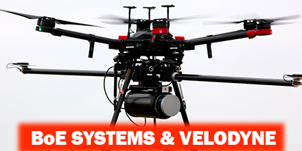
Late last year, Velodyne LiDAR Inc., the world leader in 3D vision systems for autonomous vehicles, created a partnership with BoE Systems. Velodyne integrated its VLP-16 Puck and Puck LITE 3D LiDAR sensors into BoE Systems’ UAV fleet for geospatial data collection and analysis. With this integration, BoE Systems now offers full 360° imaging of geography and equipment that serve a multitude of industries. These services meet a growing need for quick, safe, and accurate aerial inspections. Such industries, include: transportation, utilities, telecommunications/infrastructure, construction, aggregate, forestry, and agriculture.  

Tailored Solutions

BoE Systems acquires imaging data, processes it, and provides customers tailored analysis and inspection reports. This information allows companies to address immediate as well as future needs and compliance issues. In addition, BoE Systems’ proprietary hardware and software integrations provide highly detailed digital maps. Such detail allows for the development of highly accurate flood models, drainage analysis, Building Information Modeling (BIM), contour mapping, and more. “UAV mapping is a nascent industry that has quickly evolved with the adoption of LiDAR sensor technology,” said Mike Jellen, President and Chief Commercial Officer, Velodyne LiDAR. “With BoE Systems’ integration of Velodyne’s advanced VLP-16 Puck and Puck LITE sensors, the result is an incredibly valuable service that quickly and accurately maps geography and equipment to save customers critical man-hours, cost, and effort.” “BoE Systems’ hardware and software integrations leverage cutting edge technology like Velodyne’s VLP-16 LiDAR sensors to produce highly accurate 3-dimensional environmental models for industry professionals,” said Jason Littrell, President, BoE Systems. “Those professionals appreciate that our systems can do the job quickly, safely, accurately, and without breaking the bank.”  

Shop BoE Systems' LiDAR solutions at Unmanned Systems Source.


About Velodyne LiDAR

Founded in 1983, Velodyne is a technology company known worldwide for its real-time 3D LiDAR sensors. The company evolved after founder/inventor David Hall developed the HDL-64 Solid-State Hybrid LiDAR sensor in 2005. Velodyne emerged as the unmatched market leader of real-time 3D vision systems. Its products range from the high-performance, surround view UltraPuck™ VLP-32, classic HDL-32/64 and cost-effective VLP-16, to the upcoming, hidden Velarray™. Velodyne’s rich suite of perception software and algorithms are the key enablers of its perception systems.  

About BoE Systems

BoE Systems integrates cutting-edge hardware and software to provide highly accurate geospatial data collection solutions. BOE's drone-based aerial LiDAR systems create detail-rich 3D models for a variety of industries. Analytics are applied to determine critical data points such as geodetic locations, slope identification, point-to-point measurements, volumetrics, and more. BoE models are perfect for creating digital elevation models, overlaying contour lines. Additionally, these models even support predictive analytics such as flooding and drainage analysis.

Altavian Announces Work with NASA at UAS Test Site

Altavian, recently announced that it is working with Northern Plains UAS Test Site (NPUASTS). The reason? Altavian is helping to test NASA's Unmanned aircraft systems Traffic Management (UTM) system. Altavian and NPUASTS are developing technology related to UTM. Additionally, a third partner, iSight RPV Services, is providing flight test services on the Nova F7200 sUAS.  

UTM History

In recent years, NASA has worked with technology leaders in the sUAS industry to develop a UTM system which safely integrates drones into the national air space. A UTM is integral to regulating drones on a national level, as well as beyond visual line of sight (BVLOS) operations.  

Developing UTM Technology

Altavian is hard at work developing dual communication systems for the Nova F7200. Point-to-point radio frequency communication is the most common method for sUAS-to-operator communication. Currently, nearly every drone uses point-to-point. This technology is optimal for high-rate aircraft telemetry or payload links, such as HD video. However, it has limitations when the sUAS is flown further away from the operator. By implementing a satellite link, the sUAS can send low-rate telemetry messages back and forth to the operator anywhere in the world. As such, the sUAS's range is no longer limited by local radio frequency. In parallel to this, Altavian is updating its Ground Control Station software, Flare, to communicate with the updated UTM system. Previously, Altavian and NPUASTS conducted flight tests with Technical Capability Level 1 in early 2016. The upcoming tests are the third iteration of the UTM system. By integrating Flare with the new UTM system, NASA is able to see where Altavian aircraft are at all times during testing. This developing technology could prove invaluable to preparing Altavian sUAS for future BVLOS operations. The project will continue into April 2018.   Shop Altavian's line of vehicles at Unmanned Systems Source.  

About Altavian, Inc.

Altavian designs and manufactures high quality drones to carry the best sensors into the toughest environments. Our drones feature modular systems to carry custom and integrated payloads to specialize any drone for any type of data. Our focus is on systems that collect data with the highest integrity and accuracy.  

Easymile Autonomous Shuttle Makes History

On March 6, an EasyMile autonomous shuttle bus became the first driverless vehicle to operate on California roads. This marks the first time the California Department of Motor Vehicles (DMV) allowed a shared autonomous vehicle to travel on public roads. “This is the first driverless shuttle in California that DMV has granted this permission,” said Jessica Gonzalez, DMV spokesperson. “It's a really big deal.” Testing centers around Bishop Ranch, the largest mixed-use business community in San Ramon, California.  

Ideal testing ground

Bishop Ranch is an ideal test site. The 585-acre office park hosts approximately 30,000 workers, many of whom use BART for the commute. However, to get to Bishop Ranch from the nearest BART station, users board shuttles which make over a dozen stops. As such, many users find the commute inefficient and inconvenient and, thus, choose not to use public transportation. County transit planners hope shuttles, such as the EasyMile, change all that. If this latest phase is successful, the hope is to roll-out dozens of EasyMile shuttles. These shuttles will offer individual routes that stop only once. In the future, planners envision routes that go into neighborhoods to pickup city-bound commuters headed to BART.  

Pilot program

The Contra Costa Transportation Agency (CCTA) leads the pilot project. The manufacturer, EasyMile, specializes in autonomous vehicle technology. The test is possible thanks to state legislation passed in 2016, Assembly Bill 1592. The bill approved regulations governing the driverless testing and public use on California roads. Before hitting the public roads in San Ramon, the shuttle bus successfully completed two phases of testing. These test vehicles are not equipped with a steering wheel, brake pedal, or an accelerator. Currently, the vehicles are staffed by trained testers. “We will look back on this permit as a turning point for autonomous vehicle technology in the great state of California,” said CCTA Executive Director Randell Iwasaki. “It is a huge step for safely developing a solution to the challenges that prevent people from using public transportation. It will transform how we travel in Contra Costa and beyond.” Starting April 27, users in the Bishop Ranch area can experience driverless shuttle service on a limited basis. For now, an attendant is on board to answer questions and push the emergency stop button, if needed.  

Autonomous shuttles

Shared autonomous shuttles offer safe, accessible service that may provide first- and last-mile transit solutions. Future use areas include: office parks, campuses, suburbs, and town centers. Additionally, autonomous shuttles offer environmental benefits. Low-speed autonomous shuttles can help ease congestion, reduce harmful emissions, and provide affordable access to transportation hubs. In the coming year, select employees from businesses within Bishop Ranch, will ride the shuttles as testers and evaluators. The permission for the EasyMile shuttles from the California DMV is separate from their autonomous vehicle testing program that has been underway since 2014.

How GPS brings time to the world

Knowing the correct time is something we take for granted. But, who exactly decides the correct time in the first place? How does anyone go about determining the correct time? And, how does GPS fit in to the story?

Ultimately, the International Bureau of Weights and Measures (BIPM, Paris) determines the correct time.

To determine the time, BIPM in Paris relies on contributions from a worldwide collaboration of timing laboratories. Each of these laboratories maintain their own measure of time and compare it with GPS time.


One clock to rule them all

Timing labs employ precise clocks. To measure time precisely, Cesium atomic clocks and Hydrogen masers are among the most popular devices.

Although these clocks are very reliable -- accurate to about 2 nanoseconds per day -- small variations still occur. At BIPM in Paris, they compare the performance of clocks in timing labs from around the world. They use a weighted average of all contributions and calculate Coordinated Universal Time (UTC).

Interestingly, labs with better performing or more stable clocks receive more weight in the UTC calculation.

This means that real-time UTC is only an approximation... albeit a very accurate one. Thus, they determine the more precise calculation in retrospect.

The Circular-T journal, published monthly by BIPM, contains the small corrections. They apply these corrections to UTC for the previous month.

GPS receivers and time

Each timing lab contributing to UTC measures its own version of UTC. For example, UTCBrussels is the Belgian measure of UTC.

So how does BIPM compare the performance of all these different clocks?

It uses GPS receivers. Or, more accurately, GNSS (Global Navigation Satellite System) receivers which - in addition to GPS -- track constellations, such as: GLONASS, Galileo, BeiDou and IRNSS.

The precise measurement of time is at the heart of every GPS receiver.

They determine the distances between satellite and receiver, used to calculate position, by measuring the transit times of the satellite signals to the receiver.

An error of 1 nanosecond in the transit time translates into an error of 30cm in the distance.


Flying clocks

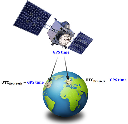
The GPS satellite constellation uses its own precise measure of time called: GPS time. Each GPS satellite has its own, on-board set of atomic clocks. Thus, satellites are also very accurate flying clocks.

By tracking a GPS satellite, a receiver can record the time differences between its own receiver clock and the satellite clock, e.g. UTCBrussels - GPS time.

The time differences, along with other information, are in a data format called CGGTTS and sent to BIPM. Using CGGTTS and other data, BIPM compares a clock in Brussels with a clock in New York by subtracting the individual differences with GPS time. As such, this technique is known as "common view".

UTCBrussels - UTCNew York = (UTCBrussels - GPS time) - (UTCNew York - GPS time).

The two GPS time terms above cancel each other out leaving the difference between UTCBrussels and UTCNew York.

Setting up a timing laboratory

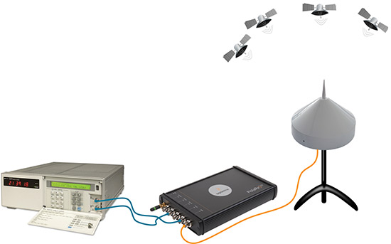
In order to compare the atomic clocks used in timing labs around the world, they need to connect to a GPS timing receiver. A GPS timing receiver uses an external atomic clock instead of its own clock; which it does by using two output signals from the atomic clock:

  • a pulse every second synchronised to UTC (PPS IN) and
  • a 10 MHz frequency reference that is essentially a sine wave (REF IN)

Figure 3 depicts the basic ingredients of a timing laboratory.

However, to reach the nanosecond accuracy required, it takes a great deal of expertise and preparation.

Signal delays in all elements in the setup require accurate calibration. To do this, BIPM maintains a set of pre-calibrated travelling receivers as calibration references.

As well as providing 1/3 of the timing receivers used for the calculation of UTC, Septentrio also provides BIPM with timing receivers for calibration.

Pushing the boundaries of science

Beyond defining and disseminating UTC, GPS timing receivers are staking their place at the forefront of science.

For example, take the case of the T2K experiment. By precisely measuring the transit time of neutrinos between two locations, limits are placed on their mass. Thus, it sheds more light on the nature of these elusive particles.

At the other end of the size spectrum, the Very-Long-Baseline Interferometry (VLBI) technique uses radio telescopes at distant locations. These telescopes are linked together in networks by time-synching their observations using GPS common view. The resulting resolution is far in excess of anything that can be achieved by any single telescope on its own.

GPS technology continues to find new ways to improve our world and advance our knowledge of it.

Shop Septentrio's line of receivers at Unmanned Systems Source.

Red Bull Air Race Selects the VectorNav VN-300 for Onboard Telemetry

The VN-300 is now the primary source for telemetry data for Master Class race planes participating in Red Bull's Air Race World Championship. The 2018 inaugural season event, in Abu Dhabi, marked the first time all 14 aircraft used the VN-300. The VN-300 provides real-time telemetry data which teams use for a variety of functions.  

About the Red Bull Air Race

Created in 2003, the Red Bull Air Race World Championship features the world's best race pilots. It is a pure motorsport competition combining speed, precision and skill. Using the fastest, most agile, lightweight racing planes, pilots hit speeds of 370 km/h. Pilots endure forces up to 10 G as they navigate a low-level slalom track marked by 25-meter-high, air-filled pylons. Pilots receive time penalties for various infractions. Such penalties include: hitting pylons, incorrectly passing through the Air Gate, as well as others. Spectators need a reference to see the difference between the pilots’ lines and speed through the racetrack. As such, Red Bull Air Race Live TV utilizes an augmented reality (AR) solution known as the Ghost Plane. The AR displays the trajectory of the pilots’ runs and provides real-time comparison in the head-to-head rounds and finals. The Ghost Plane is driven by the position, velocity and attitude data gathered during flight from the on-board INS. Critical to the success of the Ghost Plane is the accuracy of the telemetry data. And, given the high dynamics experienced during flight, is difficult to obtain.  

Importance of accurate telemetry data

For example, when a plane races through a chicane and into a vertical turn maneuver, it loses GPS signals. As such, until GPS is reacquired, the INS relies solely on the inertial sensors to provide position and velocity. “We evaluated several different inertial navigation systems. We struggled to find one that performed in our dynamics. VectorNav’s VN-300 was the only product able to deliver the attitude, position and velocity data accuracy we require. And, it did this out of the box, no customization required. The sensor is really amazing,” said Alvaro Navas, Sport Technical Manager for the Red Bull Air Race.  

VN-300

Weighing less than 30 grams, the VectorNav VN-300 is the world’s smallest dual antenna GNSS-aided INS. It is used in many applications: from autonomous vehicles to antenna pointing for satellite communication and aerial surveillance. “We are really excited to work with Red Bull Air Race,” said Gordon Hain, VectorNav Product Manager. “We provide accurate data for the race judges and spectators and we provide valuable information to pilots and tacticians. With the VectorNav data in hand they can compare actual flight trajectories with their simulations to find areas for improvement. We look forward to working with Red Bull Air Race in the 2018 season and beyond.”  

Shop VectorNav Technologies' line of sensors at Unmanned Systems Source.


About VectorNav Technologies

VectorNav Technologies is the leading innovator and manufacturer of embedded navigation solutions using the latest in MEMS inertial sensor and GPS/GNSS technology. Since its founding in 2008, VectorNav has provided systems integrators in the military, aerospace, marine, and robotics industries around the world with SWaP-C optimized, high-performance navigation systems. Furthermore, VectorNav has unique expertise in applying the digital filtering and sensor calibration techniques that have multiple decades of heritage in aerospace applications to the state of-the-art in MEMS inertial and GPS/GNSS technology.  

About Red Bull Air Race

Created in 2003, the Red Bull Air Race World Championship has held more than 80 races around the globe. The Red Bull Air Race World Championship features the world’s best race pilots in a pure motorsport competition that combines speed, precision and skill. In 2014, the Challenger Cup began to help the next generation of pilots develop the skills needed for potential advancement to the Master Class that vies for the World Championship.
GPS Spoofing: is your high-end receiver safe from an attack?

Threats from jammers have long worried GNSS users. And, now, a new GNSS bogeyman is here...spoofers. Unlike jamming, which attempts to block GNSS signals, spoofers are altogether far more sinister.

By replicating GNSS signals, a spoofer can fool a receiver into thinking that it’s elsewhere in either time or location.

And, given a growing reliance on GNSS technology for positioning and timing, it’s not hard to imagine the potential havoc a spoofing attack might cause.


$150 SDRs bring spoofing to the masses

Traditionally, spoofing is an expensive pursuit. A GPS simulator, with a price tag in the tens of thousands of dollars, is usually enough to put off most would-be spoofers.

But the now affordable price of this technology is changing the landscape.

In 2013, a team of researchers from the University of Texas commandeered a 213‑foot yacht using $3,000 worth of equipment.

The arrival of cheap Software Defined Radios (SDR) and open-source code availability is making spoofing more accessible.


Signs of spoofing

If a smartphone provides positioning, the first inkling of a spoofing attack is the phone reporting an obviously wrong location.

Figure 1 shows an example of an attacker spoofing an iPhone6 into reporting its position at the top of Mount Everest.

It was harder to spoof an Acer Android phone. The Acer uses additional positioning information from WiFi and the cellular network.

During this test, the phone owner’s wife was alerted via Facebook that he had left the country.But, spoofing a trip to North Korea might have a slightly less amusing outcome.

In the case of high-end receivers that use multiple frequencies from several satellite constellations, spoofing is more challenging. Below are signs to look for if there is suspicion of spoofing.


1) The spoofed signal is visible in the RF spectrum

The low power of GPS signals means that they are barely discernible from the thermal noise background.

In order to spoof a receiver, the SDR signals are transmitted with a much higher power making them clearly visible above the background as Figure 2 shows.

2) Divergent code minus carrier behavior

Over short time frames, satellite distances measured using the code and carrier phase of the satellite signals should show very little difference - Figure 3 (upper panel).

This behavior is difficult to replicate. So, spoofed signals exhibit a difference that can increases rapidly over a short period of time - Figure 3 (lower panel).

3) Incomplete and inaccurate nav data

Spoofed satellite navigation data is often missing the GPS constellation almanac and is still only a vague match for the real navigation data.


4) Jamming of Glonass and/or L2

Spoofing techniques are advancing but at the moment, only the GPS L1 signal is spoofed so a common tactic is to additionally jam the L1 Glonass frequencies and the L2 band. This will manifest as a sudden fallback to a GPS only standalone mode.

What can receivers do about spoofing?

As shown, single-frequency, low-end devices and smartphones are relatively easy to spoof. High-end multi-frequency receivers aren't so easy. These high-end receivers offer a number of tricks to detect spoofing.

However, in the event such a receiver detects spoofing, what exactly can it do?


1) Signal integrity alerting

High-end receivers have the option of employing spoofing flags. As such, the receiver can alert the user if it detects a spoofing attack directly in the RF spectrum or in the GPS measurements.


2) Frequency diversity

If the receiver detects spoofing on one frequency, it can switch to using measurements from other frequencies. Thereby, effectively ignoring the spoofed frequency.

Figure 4 shows this technique in action.

Three receivers are subject to GPS L1 spoofing. As the spoofer power increases, the Septentrio AsteRx4 receiver detects the spoof on L1. At this point, it switches from an L1/L2 to an L2/L5 PVT and successfully maintains an accurate position.

The other multi-frequency receiver also detects a problem. However, it has no alternative dual-frequency solution so simply stops outputting a PVT.

The L1-only module, with no detection mechanisms, switches to tracking the spoofed signal and its position gets spoofed.

3) Inertial sensor integration

An IMU device, either coupled to the receiver or mounted on the board itself, provides a unambiguous check for spoofing. In the presence of spoofing, IMUs can also provide input for an integrated PVT solution to mitigate the effects of spoofing.


Staying one step ahead

High-end GNSS receivers, particularly those employing spoofing detection and mitigation methods are still relatively safe from spoofers.

However, the increasing sophistication of both hardware -- in the form of SDRs and open-source software -- means there’s no room for complacency.

Are you spoof proof? Learn more about Septentrio's line of high-end, multi-frequency receivers.