Vendor News

Choosing the Right RF Filter for Your Application

Choosing the right RF Filter for your application can feel like a daunting task. After all, there are numerous options available. As such, when choosing an RF filter for your communications system, test and measurement setup, or RF module design, the best option depends on your specific application. Below are some key parameters to help guide your decision:
  • The frequency range(s) that shall pass through the filter (i.e., the passband)
  • The frequency range(s) that shall be rejected by the filter (i.e., the stopband)
  • The signal power level that will pass through, or be rejected by the filter
  • The amount of attenuation allowable in the passband (i.e., insertion loss (IL))
  • The amount of rejection required in the stopband(s)
  • The limitations on the physical size of the filter
  • The cost target for the filter
While there are many types or “topologies” of filters to choose from, the majority of NuWaves’ filter designs fall into three major categories: cavity, microstrip or stripline, and lumped element.  

Cavity filters

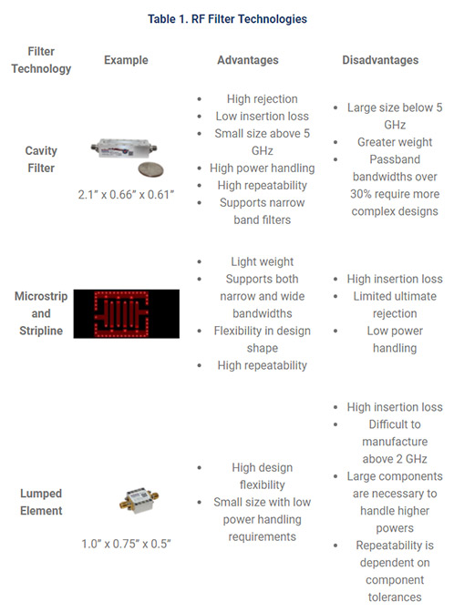
Cavity filters provide the lowest insertion loss and greatest ultimate rejection of the three topologies and are capable of handling high levels of RF power (tens of watts to hundreds of watts). At radio frequencies, the materials used in filter construction impact the performance of the filter. Printed circuit board (PCB) materials have dielectric losses that increase the insertion loss of the filter and reduces the Q-factor of the filter (how sharply the filter transitions from the passband to the stopband). For cavity filters, the dielectric is air, which is essentially lossless. Additionally, cavity filters are constructed from metals such as steel, aluminum, or brass, which shield the signal within the filter from other signals and interference from the outside. This provides a high amount of ultimate attenuation. The cost of a cavity filter, in general, is higher than that of other topologies. These filters are typically CNC machined, and require a skilled technician to properly tune the filter during assembly. See Table 1 below for the advantages and disadvantages of each topology.


Microstrip or stripline filters

Microstrip or stripline filters are printed on PCB substrates, using microstrip transmission lines (printed on the top or bottom layer of the PCB), or stripline transmission lines (printed on an internal layer of the PCB). These filter topologies are good choices for filtering between gain stages, post frequency mixers to eliminate the image frequency, as well as output filters. The ability to integrate the filter directly into the PCB greatly reduces implementation cost and simplifies the manufacturing process. [The real cost is in the designer’s labor]. Also, the filters may be printed on individual daughter boards and simply soldered to the main PCB. The performance of the filter heavily depends on the PCB substrate. Low-cost FR-4 type substrates will perform adequately at frequencies up to 1 GHz. However, as frequency increases, the loss due to the substrate becomes a critical factor. Therefore, higher quality, low-loss microwave substrate is necessary at microwave frequencies (i.e., frequencies greater than 1 GHz). The cost of microstrip or stripline filters can be quite inexpensive when designed into the PCB of the RF Module. Surface mount, drop-in, or connectorized modules will be more expensive, but less than cavity filters. Microstrip filters suffer from low ultimate rejection (-25 dB to -40 dB) due to the fact that the microstrip traces are exposed on the outermost layer of the PCB. The ultimate rejection can be improved by enclosing the filter with an RF shield. Stripline has a higher ultimate rejection because the traces are sandwiched between two groundplane layers inside the PCB. Substrate losses are greater with stripline than microstrip, because the traces are completely enclosed in substrate, where microstrip is half substrate, half air. In general, microstrip and stripline filters can handle several tens of watts. Insertion loss values are typically 1 dB to 4 dB, depending on passband bandwidth (narrower bandwidth with have more loss), and the selectivity of the filter. The physical size of these filters is dependent on frequency, where the traces are typically ¼ wavelength long. This dependency makes the filters impractically large below UHF frequencies, unless miniaturization techniques are employed.  

Lumped element filters

Lumped element filters are a good option for filtering below 1 GHz, where cavity filters and microstrip/stripline filters may be prohibitively large. The term “lumped element” refers to the use of capacitors and inductors (i.e., physical components or “lumps”) to create the filter response. The physical size of lumped element filters is mostly driven by the power handing required. A low power handling requirement, such as < 10 mW, may be constructed of the smallest components available (0201 or 0402 sized components for example). While a requirement for hundreds of watts would require inductors and capacitors capable of handling the high current and voltage of the system. Similar to the microstip/stripline filters, lumped element filters may be integrated into the PCB design, integrated as a surface mount daughterboard, as a drop-in component, or a connectorized package for internal or external integration. The cost of a lumped element filter is similar to that of microstrip or stripline filters. Passband insertion loss of lumped element filters varies greatly depending on the quality of components (Q-factor), selectivity required, and type of filter response (highpass, lowpass, bandpass, etc.). Therefore, the passband insertion loss is typically in the range of 0.5 dB to 5 dB. Ultimate rejection also varies, from up to 70 dB for a filter with a traditional Butterworth or Chebyshev response, to 25 to 35 dB for a bandpass filter with an elliptical response (high selectivity and low passband insertion loss (~1.5 dB typical) with lower ultimate rejection). A disadvantage to lumped element filters is high frequency performance, as capacitors and inductors are limited by the self-resonance frequency of the component. Self-resonance frequencies become a design concern above 1 GHz, and very few components have self-resonance frequencies above 6 GHz.
 

Choosing an RF Filter

RF Filtering is a key component of any communications system to eliminate interference and out-of-band emissions. There are many types of filters to choose from, but by identifying the key parameters that are important to your design, the choices can be narrowed down significantly.   Shop NuWaves Engineering's complete line of RF Filters at Unmanned Systems Source.

VectorNav INS Selected for UAV LiDAR Mapping System

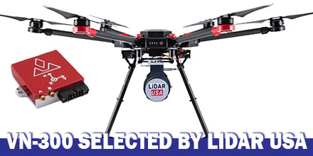
LiDAR USA announced the integration of  VectorNav's VN-300 Dual-Antenna Inertial Navigation System f0r its ScanLook Revolution UAV-based  mapping-system. The combined system provides LiDAR mapping capabilities targeted at applications that require a fast, efficient and easy-to-use solution.  

UAV-based LiDAR

Historically, the size, weight and power requirements of legacy LiDAR mapping systems primarily limited their use to manned aircraft. Plus, to keep costs feasible only large areas were best for mapping. Thanks to advances in both LiDAR and INS technology, a new generation of mapping systems are emerging. Today, LiDAR units weigh just a few hundred grams and can fit in the palm of the hand. They are also affordable enough for small businesses to develop services with a meaningful return on investment.  

How it works

Mobile LiDAR mapping requires several components to work synergistically in order to provide a suitable output. Components include: a LiDAR scanner, attitude/orientation sensor, positioning system, timing reference system and a vehicle or mobile platform. Traditionally, users had to either piece all the components together. Or users had to buy expensive systems designed for survey applications which incorporated L1/L2 GPS receivers with RTK positioning techniques. These types of systems also required the added expense of communicating with a reference base station or reference network system in order to maintain such accuracy. Clearly, there was a growing need for a low-cost, easy-to-use mapping system available to a wide-range of users. A system that required no advanced training, or complex setup and expensive post-processing. Enter LiDAR USA. Leveraging 18 years of experience, LiDAR USA developed the ScanLook Revolution system.  

Why VN-300?

LiDAR USA selected the VN-300 Dual-Antenna INS to keep the Revolution small, accurate and fully featured. “The VN-300 stood out among the rest for it’s exceptional performance in a wide range of operating conditions and especially for its small size and low weight. The VN-300 is a powerful sensor,” said Jeff Fagerman, CEO of LiDAR USA. “It’s tiny, only weighs 30 g and has performance comparable to much higher-priced systems,” In part, LiDAR USA selected the VN-300 because it does not rely on magnetometers for heading estimation. “Relying on magnetometers for accurate heading estimation is typically highly problematic,” according to Jakub Maslikowski, Director of Sales and Marketing at VectorNav. The VN-300 uses two GNSS receivers and a technique known as Carrier Phase Interferometry. This technique enables the VN-300 to estimate the heading solely from GPS signal measurements when the vehicle is stationary. Development of the Revolution was a challenging endeavor and required a lot of experimentation and fine tuning. “Working with the VN-300 and the team from VectorNav has been excellent. They’re responsive, extremely knowledgeable and a great team to work with,” said Fagerman.  

Shop VectorNav's entire line of solutions at Unmanned Systems Source.

FT Technologies Announces New, Lightweight Wind Sensor for Use on Drones, UAVs

FT Technologies announced the launch of the first in a new generation of lightweight ultrasonic wind sensors -- the FT205. Made from a graphite and nylon composite, and weighing only 100g (3.5oz), the FT205 is designed specifically for use on drones and unmanned aerial vehicles (UAVs).  

FT205 Technology

Powered by FT’s unique Acu-Res® Technology the sensor uses ultrasound to derive air speed, direction and temperature. It also features a built-in compass. Although light, the compact size and shape of the FT205 makes it physically very strong. It is resistant to vibration, shock, electrical interference and is also fully-sealed and water-resistant. It can operate at altitudes up to 4000m and at temperatures between -20°C and +70°C. With low power requirements, and reading wind speeds up to 75m/s, the FT205 is ideal for UAV flight control systems and environmental monitoring from drones and remotely piloted aircraft.  

Mount options

To provide accurate wind measurements, the wind sensor must be mounted away from the wash of the drone rotors. Every drone is different so the FT205 is designed to fit either to a pole or to flat surface. It can also be mounted upside down. It can output data via RS485, RS422 or UART. Units of measure can be set to metres per second, kilometres per hour or knots. “The FT205 is the first in a new generation of lightweight ultrasonic wind sensors,” said Fred Squire, Director of Sales and Marketing. “It is unique in the market in that it combines a weight of only 100g with a wind speed reading range up to 75m/s. The light weight of the FT205 together with the proven FT Acu-Res® Technology make it ideal for use on aerial drones and other applications where weight is critical.” Like all FT wind sensors, the FT205 was thoroughly tested in a HALT (Highly Accelerated Life Cycle) chamber. The FT205 was heated to +90°C and cooled to -40°C while being vibrated in six dimensions up to 60g. During and after the testing the test sensors continued to communicate accurately so it is well able to survive normal service.  

Shop FT Technologies line of sensors at Unmanned Systems Source.

Inertial Labs Releases Affordable, Multi-GNSS Constellation, 1cm RTK Accuracy Dual-Antenna GPS-Aided INS

Inertial Labs, Inc., a developer and supplier of high performance Inertial Sensors and Systems, released an affordable, multi GNSS constellation, 1 cm RTK accuracy dual-antenna GPS-Aided Inertial Navigation System (INS).  

Affordable Dual-Antenna GPS-Aided INS

The INS-DL and the OEM version, INS-DL-OEM, are multi constellation -- GPS, GLONASS, GALILEO, Beidou -- GPS-Aided INS that achieve 1 cm Position and 0.05° Heading, Pitch & Roll accuracy. These high precision and high-accuracy INS are affordably priced at around $5,000 USD. The INS-DL and INS-DL-OEM are compact and deliver high performance. They are designed for developers of autonomous and unmanned systems; vehicles and small robots for precision agriculture; payloads for remote sensing and survey applications. The INS-DL is available as a classic INS or as an advanced, GPS-aided Motion Reference Unit (MRU). As a classic INS, it outputs Position, Orientation and IMU data for real-time and post-processing operation. As an advanced, GPS-Aided MRU, it outputs Position, Velocity, Heading, Pitch, Roll, Heave, Surge, Sway and Significant Wave Height data for survey, hydrography, bathymetry and motion control. "GPS-Aided INS-DL is a result of significant efforts of our R&D team. It is a market oriented solution, geared towards applications, requiring the best combination of high performance and in a same time low cost " said Jamie Marraccini, Inertial Labs’ CEO and President.  

About Inertial Labs

This year, Inertial Labs celebrate its 17th anniversary as a developer and supplier of high quality inertial sensor based solutions for  land, marine and aerospace applications. Since 2001, thousands of inertial systems, as well as those fused with other technologies like optical, laser, and GNSS systems, were successfully delivered to our customers for AGV, UAV, AUV, UUV, robots, land vehicles etc.  

Shop Inertial Labs line of solutions at Unmanned Systems Source.

Introducing the HA32 UAV Antenna from Hemisphere GNSS

Hemisphere GNSS recently announced the launch of its all-new multi-GNSS, multi-frequency 4-helix HA32 UAV antenna. The HA32 is a high-performance antenna. It supports GPS, GLONASS, Galileo, BeiDou, and Hemisphere's Atlas L-band correction service. Designed specifically for UAVs, GIS, surveying, and RTK. It is also highly suitable for applications requiring high-precision positioning and navigation.  

Proprietary Technology

The HA32 is built on proprietary 4-helix antenna technology. It provides high filtering and anti-jamming performance with LNA features such as low noise figure of 2.0 dB (typical) and up to 30 dB gain (typical). Suitable for most outdoor and harsh operating environments, the HA32 antenna is sealed in a durable and ruggedized IP67-rated enclosure. It is also equipped with an O-ring. The lightweight (40 g typical) and compact (40 mm x 75 mm) design of the antenna makes it resistant to wind when installed on UAVs. It offers easy integration with a single SMA RF connector. “We are very excited to introduce this extremely competitive entry-level UAV GNSS antenna for a wide range of positioning and navigation applications such as UAVs, GIS, and RTK,” said Miles Ware, Director of Marketing with Hemisphere GNSS.  

Hemisphere Atlas

Hemisphere’s Atlas is a flexible, scalable GNSS-based global L-band correction service which provides robust performance and correction data for GPS, GLONASS, and BeiDou. Atlas delivers correction signals via L-band satellites to provide sub-meter to sub-decimeter level accuracy. It leverages approximately 200 reference stations worldwide, providing coverage to virtually the entire globe. Atlas is available on all Hemisphere Atlas-capable single and multi-frequency, multi-GNSS hardware. It complements third-party GNSS receivers by using Atlas corrections with Hemisphere’s BaseLink and SmartLink capabilities. Using multi-frequency hardware, Atlas creates faster convergence times, and is robust and reliable in canopy or foliage covered areas. Atlas Basic provides users of both single and multi-frequency Atlas-capable hardware the ability to achieve better than SBAS performance anywhere in the world where the Atlas correction service is available. Atlas Basic offers a proven accuracy of 30 cm (pass-to-pass 95%) to 50 cm (absolute 95%) and instantaneous sub-meter accuracy.  

Shop Hemisphere GNSS at Unmanned Systems Source.


Introducing the AsteRx-i for IMU-enhanced GNSS Positioning and Attitude

GNSS receiver manufacturer Septentrio recently announced the launch of the next generation AsteRx-i. The announcement occurred at IEEE/ION Position Location and Navigation Symposium in Monterey, US. The AsteRx-i combines Septentrio’s latest compact, multi-frequency multi-constellation GNSS engine with an external industrial grade MEMS based IMU. It delivers accurate and reliable GNSS/IMU integrated positioning to the cm-level. It also delivers full 3D attitude at high update rates and low latency.  

AsteRx-i key benefits:

  • IMU-enhanced GNSS positioning with full attitude: heading pitch and roll
  • Quad-constellation, multifrequency, all-in-view RTK receiver
  • AIM+ interference monitoring and mitigation system
  • High-update rate, low-latency positioning and attitude
Designed around demanding requirements for size, weight and power consumption, the AsteRx-i is ideal for optical inspection and photogrammetry. Accompanied by a UAS-tailored carrier board, the AsteRx-i integrates seamlessly into light UAVs. The versatility of design and range of connection interfaces extend the AsteRx-i applicability to automation and robotics as well as logistics. The AsteRx-i includes Septentrio’s GNSS+ suite of positioning algorithms to convert difficult environments into good positioning: LOCK+ technology to maintain tracking during heavy vibration, APME+ to combat multipath and IONO+ technology to ensure continued position accuracy during periods of elevated ionospheric activity. It also features AIM+ interference mitigation and monitoring system which can suppress the widest variety of interferers, from simple continuous narrowband signals to the most complex wideband and pulsed jammers. “Complementing our GNSS portfolio with an INS offering is a natural evolution of our product range. At Septentrio, we design our GNSS solutions with a focus on reliability and availability. Smart integration of inertial sensors builds on these strengths to make affordable high-precision positioning and orientation solutions possible for ever more demanding applications,” said Francesca Clemente, Product Manager at Septentrio.  

Shop Septentrio's line of products at Unmanned Systems Source.


About Septentrio

Septentrio designs, manufactures and sells high-precision, multi-frequency, multi-constellation GPS/GNSS equipment for use in demanding applications. Septentrio products are used in a wide variety of industries including marine, construction, agriculture, survey and mapping, geographic information systems (GIS) and unmanned aerial vehicles (UAVs).